…And Why Every Crew Needs One
If you’ve spent any time on a modern construction site, you’ve probably seen the antennas mounted on dozers and graders, the screens glowing in the cab, and operators grading without a single stake in the ground. That’s GPS machine control — and the 3D model is the brain behind all of it.
The Simple Explanation
A 3D GPS machine control model is a digital terrain model (DTM) loaded directly into GPS-equipped construction equipment. It contains the finished grade surfaces, subgrade layers, breaklines, and design geometry for your project. When that model is loaded into a dozer, grader, or excavator, the machine’s GPS system compares its real-time position to the design surface and shows the operator exactly how much to cut or fill — down to the hundredth of a foot.
As one industry source puts it, a GPS machine control model is “the digital brain behind modern grading and excavation equipment. It tells dozers, graders, and excavators exactly where to cut, fill, and shape the earth — without relying on stakes or guesswork.”
What’s Actually Inside the Model
A complete machine control model isn’t just a single surface. It typically includes:
Finished Grade (FG) surface — the final design elevation the project needs to match. This is what the owner, engineer, and inspector are checking against.
Subgrade surface — offset below the finished grade to account for pavement structural section. This is what the dozer cuts to so that base rock and paving can be placed on top.
Breaklines — linework that defines where the surface changes direction, like the edge of pavement, ditch flowline, curb lip, or top of slope. Without accurate breaklines, the triangulation between surface points creates unrealistic slopes that cause problems in the field.
Boundary — defines the limits of the model so the surface doesn’t extrapolate into areas it shouldn’t.
According to industry sources, these models typically include three major surface types: Digital Terrain Models (DTM) representing existing conditions, Finished Grade Models representing the final surface, and Subgrade Models ensuring foundational integrity for drainage and load management.
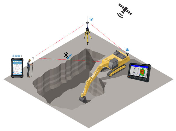
How the Equipment Uses It
GPS receivers mounted on the machine — typically on the blade or bucket — communicate with a base station or network RTK system. The system uses Real Time Kinematic (RTK) GPS to determine the machine’s position to centimeter-level accuracy. That position is compared to the design model, and the operator sees a real-time display showing cut or fill depth at the blade edge.
On systems with automatics enabled, the hydraulics actually move the blade automatically to maintain grade — the operator just steers and controls forward speed.
Why It Matters More Than People Realize
The difference between a good machine control model and a bad one shows up in production. A model with missing breaklines causes the surface to triangulate incorrectly, creating phantom humps and dips that send the operator off grade. A model with the wrong subgrade offset means the crew is cutting to the wrong depth. A model missing a section of the project means the equipment screen goes blank mid-run.
I spent over 10 years in the field depending on these models as a Leadman GPS Gradesetter. The models that worked were the ones built by someone who understood what happens when the machine starts moving — not just what the plans say.
The Bottom Line
If your crew runs GPS-equipped equipment, the quality of your machine control model determines the quality of your production. A field-ready model built from accurate plan data, with proper breaklines and surface layers, means your operators hit grade on the first pass and keep moving. A bad one costs you time, rework, and money.